Pictures:
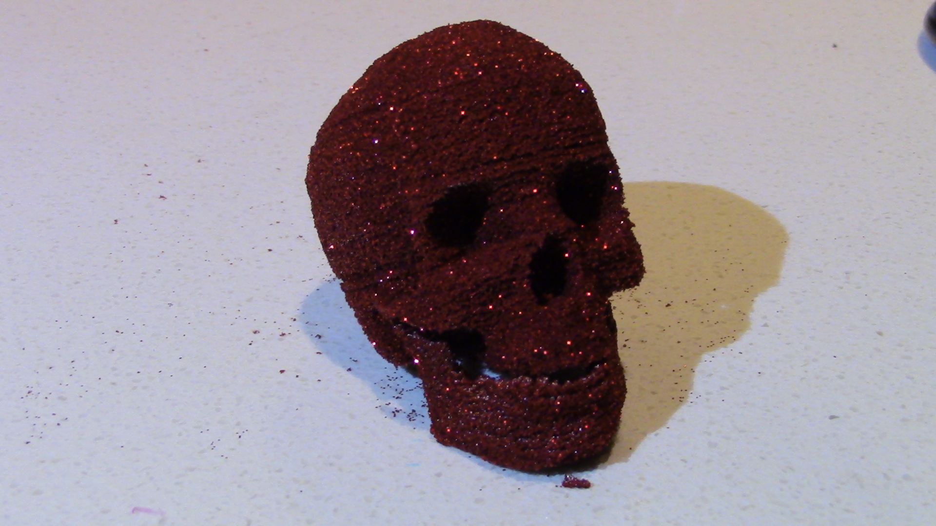
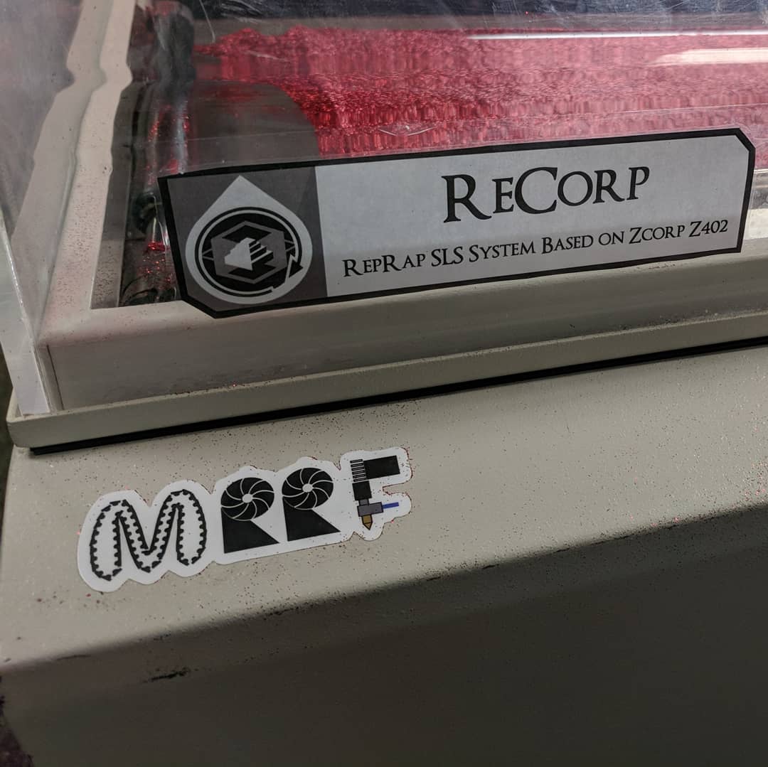
^ Skull from the ReCorp
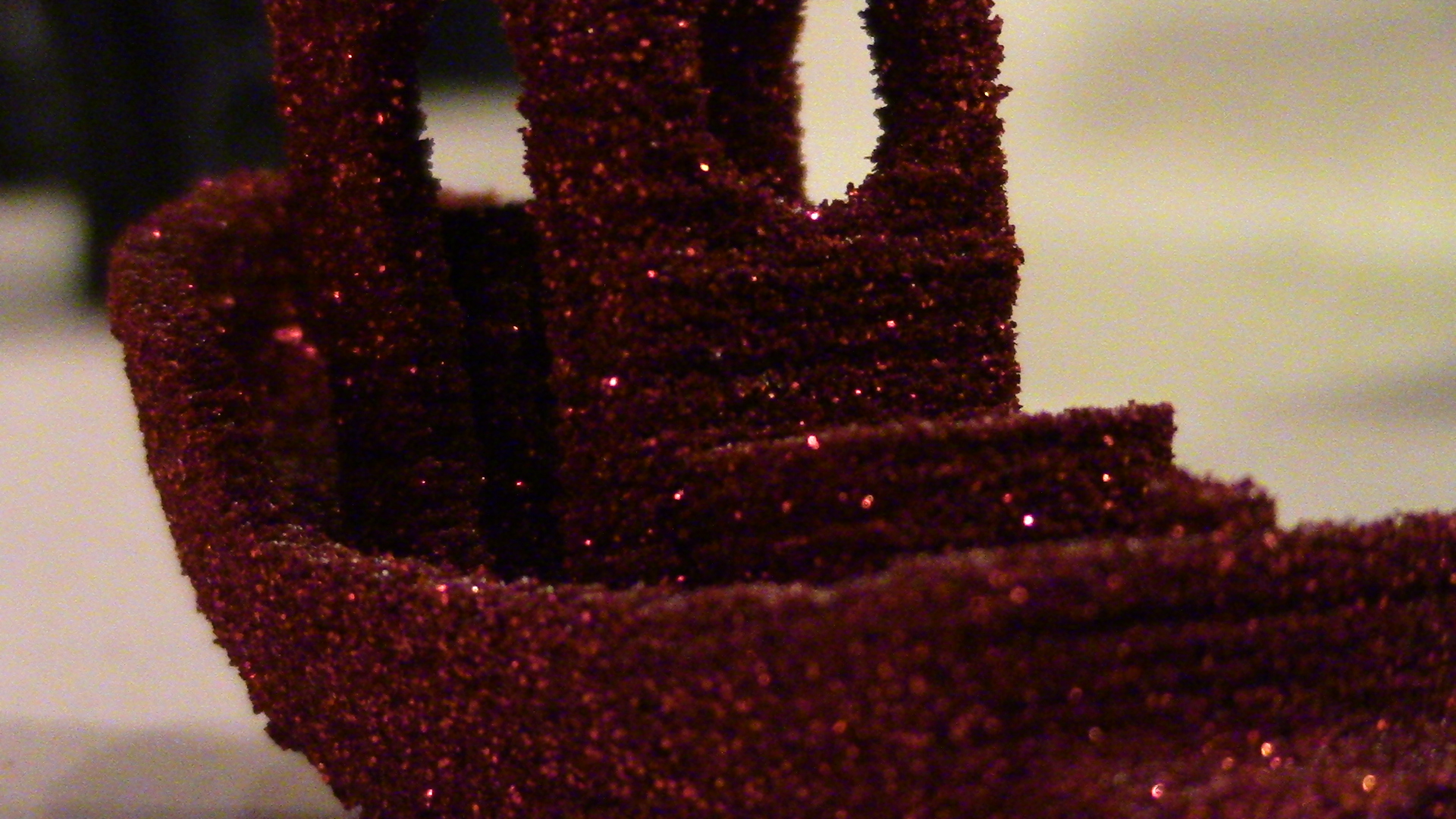
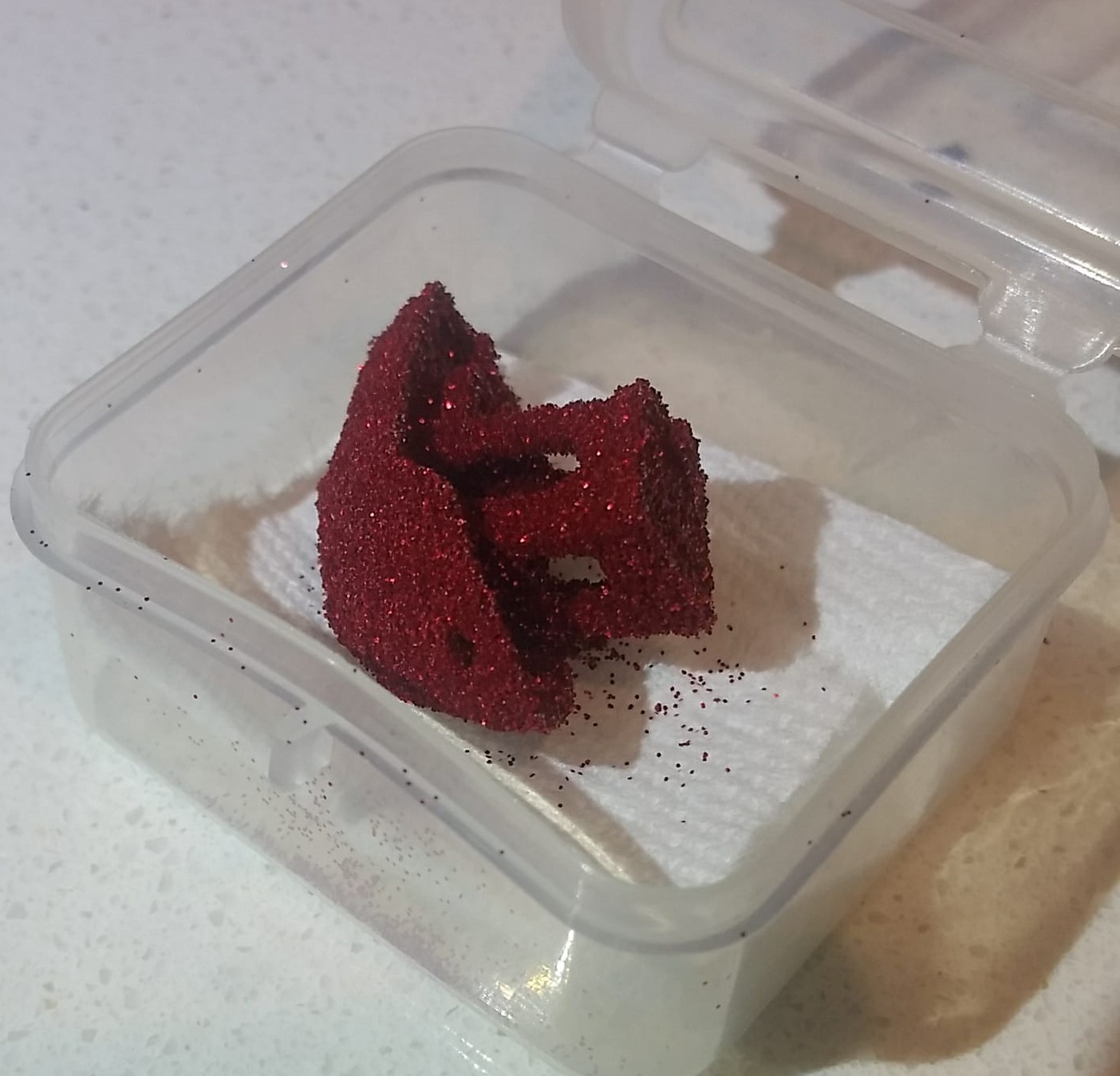
^ Backside of a #3DBenchy
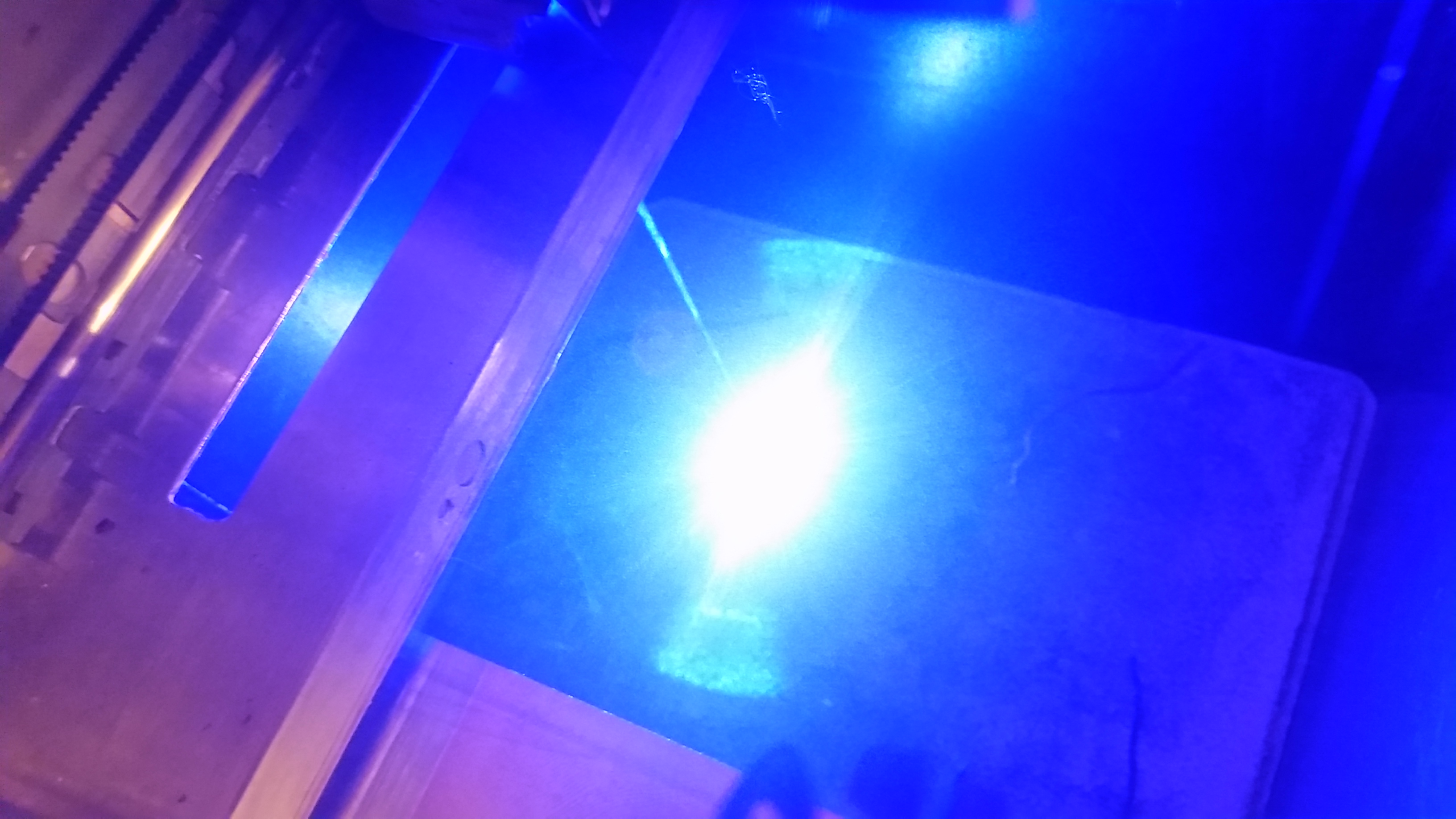
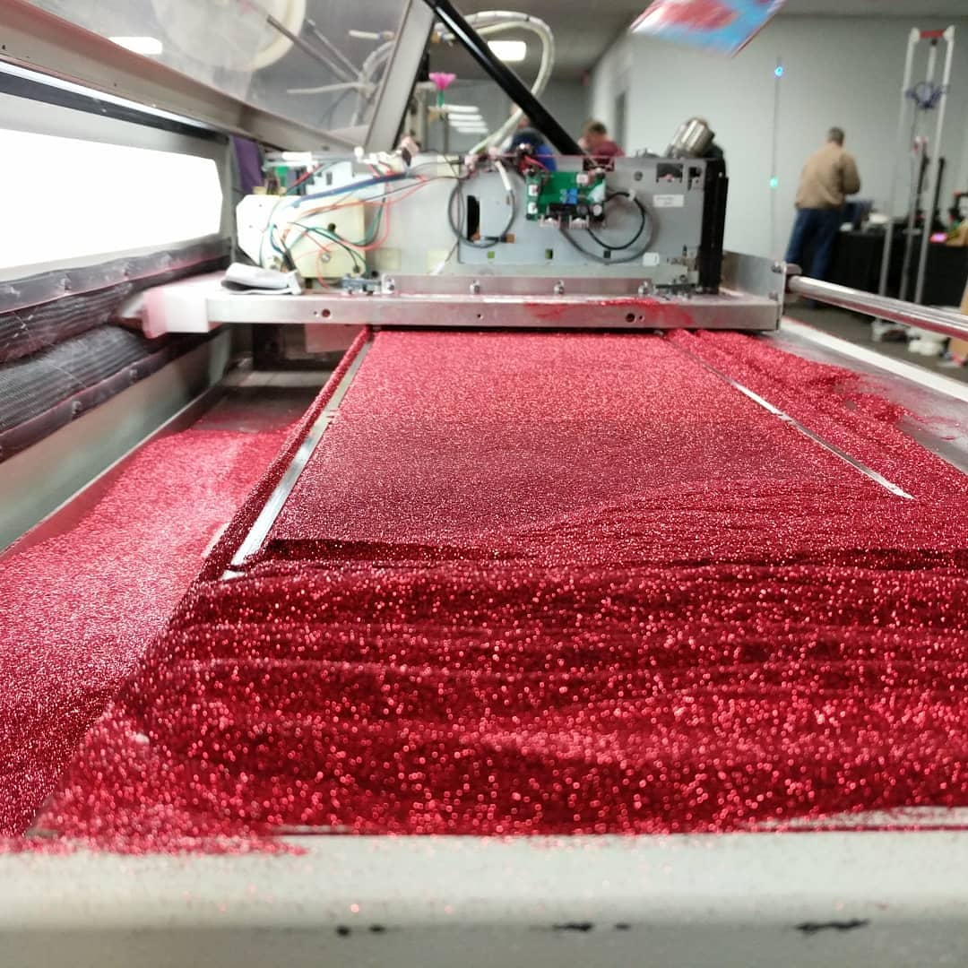
^ First Laser Test
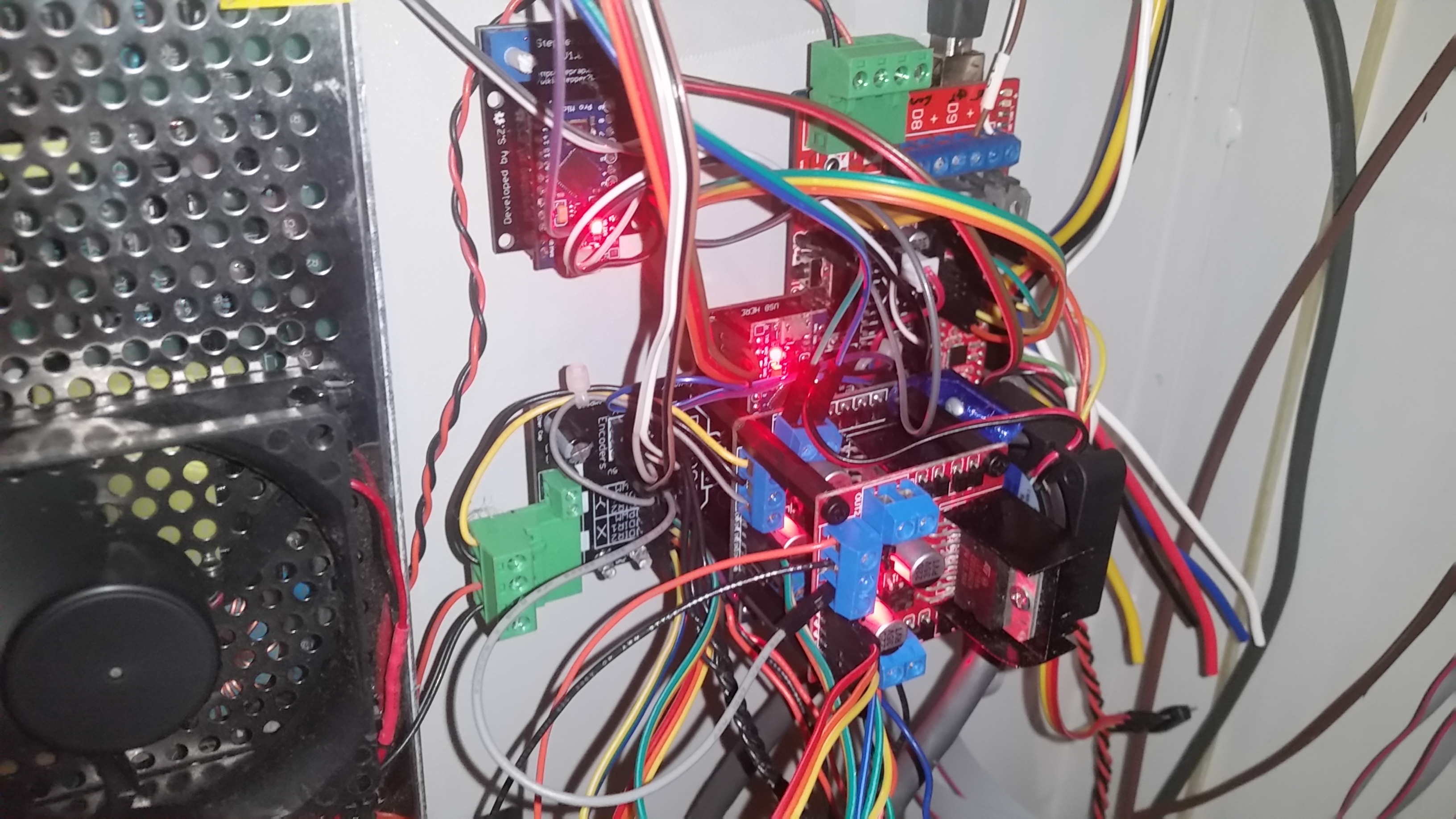
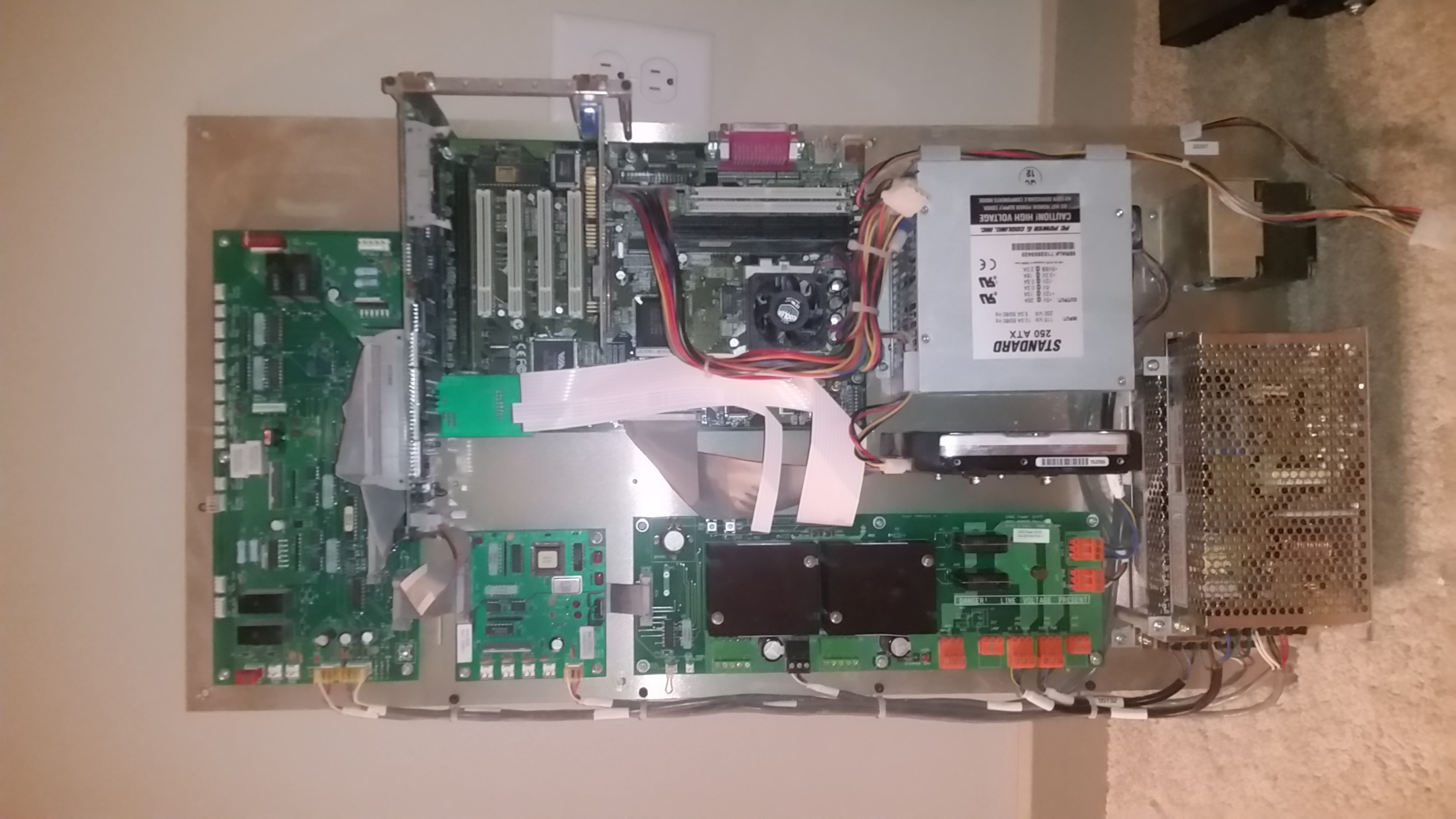
^ Control Board stack with RAMPSSB and Stepper2Laser
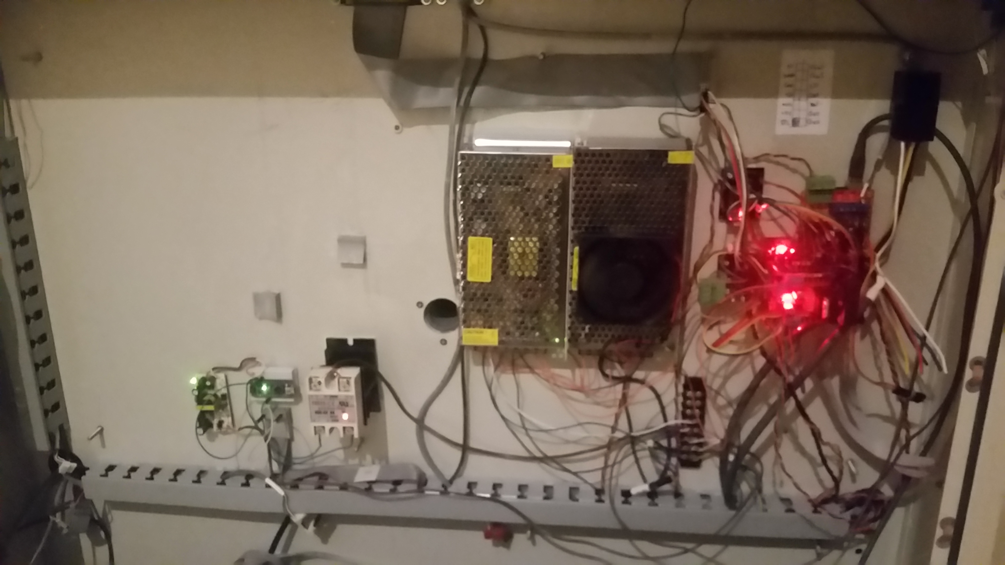
^ Electronics Housing
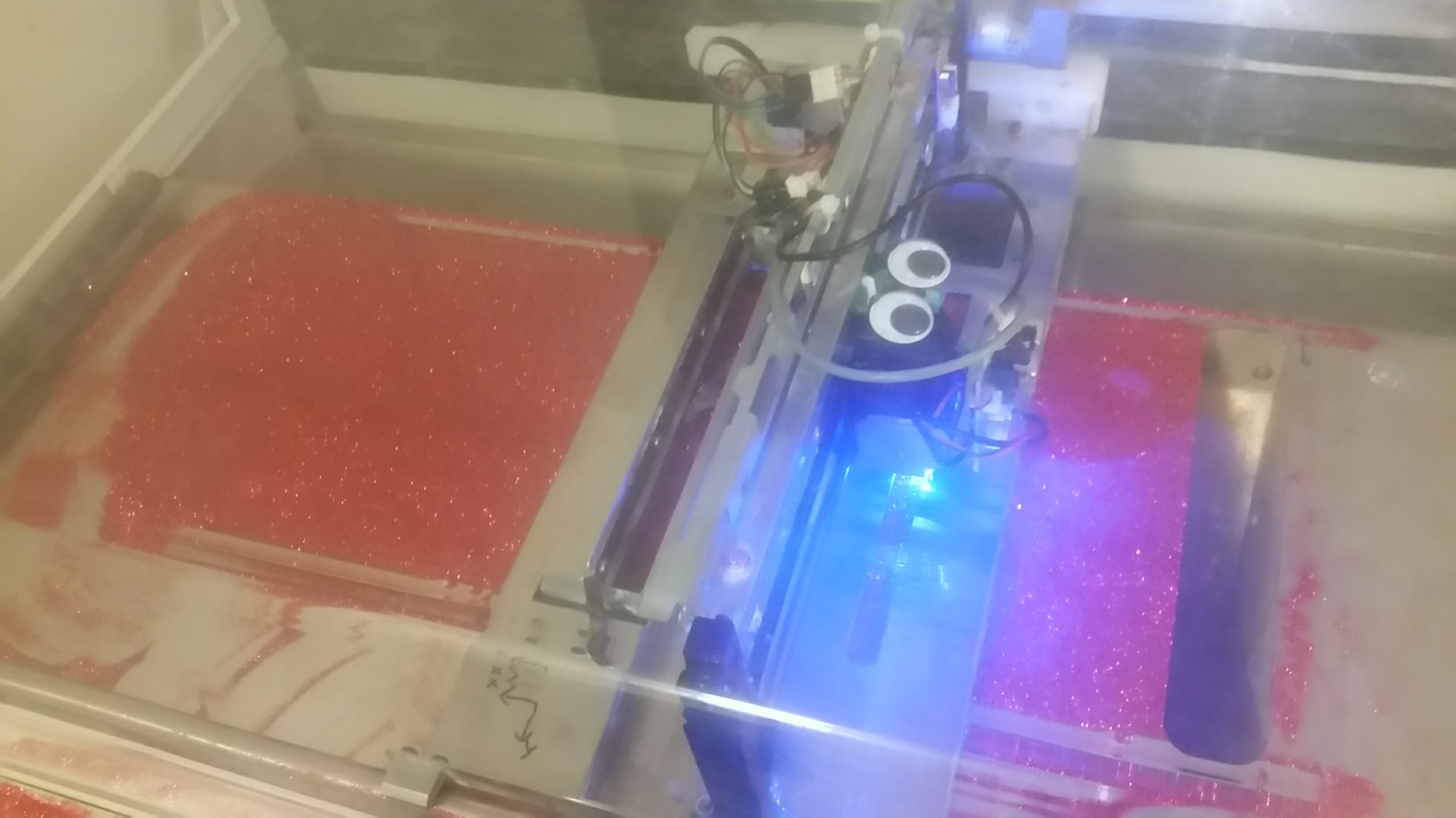
^ Two particularly messy images of the ReCorp at MRRF 2018, by OSHPark
Skills used:
Mechatronics, GCODE, Material Science, Eagle board design, Electronics, Control Theory, CAD
Description:
This is one of my favorite projects I’ve probably ever done. This story starts back. WAY back. 1997. A company called “Zcorporation” or simply “Zcorp” releases a 3D printer called the Z402. It was the first industrial machine to use an additive manufacturing process called “binder jetting.” It used an HP inkjet head, going back and forth over a bed of powder (mostly plaster), spraying a sticky “binder” and causing the powder to stick together. It would then drop down 1 layer, and spread a new layer of powder over the build. It was basically building sand castles, and the parts had very little mechanical strength, but it was able to produce a very large part very quickly, and later versions of the technology were able to print in full color. As a fun 3D printer fact, the Zcorp Z402 was probably the first machine to be called a “3D printer,” because it was using a printer head to print in 3 dimensions. What we know as 3D printers today had been around before (namely FDM, and before that, SLA) but those were, unsurprisingly, referred to as “Fused Deposition Modelers” or “Stereolithography apparati” or “Rapid Prototypers.” The term “3D printing” was first used to refer to this powder process, and Zcorp was the first company to gain rights to use the patent on the process, and the Z402 was the first machine produced by Zcorp. The term eventually consumed the rest of additive manufacturing as patents began to run out, but in 2012, Zcorp was acquired by 3D systems, who promptly wiped all their information off the face of the internet.
But the machines remain. And one such machine, a Z402, came up at my friendly neighborhood college surplus auction and I got it for a bargain. It was old, dusty, and abused to all hell, and all the binder lines were frozen, but looked mechanically intact. I took it home, cleaned it out with a leaf blower on my driveway, and then wiped the whole machine down with some paper towels, and it looked almost as good as new.
I always liked powder bed systems, and since the jetting heads had no hope of revival, I figured it would be an interesting challenge to try and convert it to an SLS (Selective Laser Sintering) machine. Typically these machines are millions of dollars, but open source versions (like Andreas Bastian’s OpenSLS, and it’s continuation, OpenDMLS) do exist. Out of respect for the machine, I didn’t want to change that much about the system, but rather take control over the system and use it how I wanted to, while retaining as much of the original hardware as possible, but while also leveraging the Reprap project’s software like Repetier.
Unfortunately, the stock control board had to go. It was based on windows DOS, with a Zcorp overlay, but was running on an old computer (like a full on desktop motherboard jammed in the back), with a bunch of custom boards driving everything. Because it was all 1997 era technology, the chances of finding a new part or reverse engineering a board was slim, and the chance a hard drive with 10MB of free space was able to run repetier was slim. I took the whole control panel out, but I have to admire the build quality. Someone spent a lot of time making sure everything was crimped, labeled, and managed perfectly. It’s really beautiful. At some point, I want to hang it on my wall.
I started fresh with some foam tape and a RAMPS board, and started solving problems from there.
First issue: The X and Y motors. The Z402 uses some old Pittman motors, but they aren’t steppers, they’re DC motors with encoders. These servo based controls I actually like better than steppers; they’re smoother, more precise, faster, and cheaper, and, if they are controlled correctly, closed loop so they can catch their mistakes. I’ve actually wanted to do something like this for a while, so I made a board, the RAMPSSB, which converted step direction signals to DC quadrature motor control. It took a bit of tuning to get them running correctly, but I managed to get them to work.
Second issue: the laser. I had an old 2W UV laser left over from the LaserRazer, but decided instead to get a new 2.5W blue laser for this project. After sourcing it, and getting it installed, I needed a way to control it. To do this, I made another board, Stepper2Laser, that reads the enable, direction, and step pins and extrudes when it gets a step AND the direction is forward AND the motor is enabled. If minimum retraction distance is set to 0, than the laser fires whenever the extruder would generally be running. This mostly works, but for small areas like points, the laser turns on and off too fast. I eventually want to compensate for this, but one step at a time (no pin intended) (no pun intended).
But then, I hit a new snag. The machine was working, but I needed powder for it. Zcorp was nothing but bones in a coffin at this point, and the price and minimum order quantity of powdered nylon was way beyond my price range. I started thinking of what material properties I would need in order to print on a powder machine. There was no bed adhesion at all, so warping was a big problem. Thinking through typical, FDM style materials, I figured PET or PETG would be the best for this, and started looking for PETG powder. Looking through industrial applications for PETG, I came across an idea. A horrible idea. I wonderfully horrible idea.
Glitter.
No, this isn’t a joke, this isn’t misleading, and this isn’t an April fools day joke, that sparkly stuff that is a mainstay of 6 year old girl’s birthday parties, christmas cards, soaps and strip clubs is almost always made of a PET film. I always thought it was foil, and while some are made of foil, some (especially the small stuff) are made of PET (well, mostly PET, some aluminum for shine, and a bit of polyurethane for coloring). Checking on eBay showed someone selling 50 lbs of red 0.008” wide hexagonal glitter for about 130 bucks, which I couldn’t resist.
After loading the material, tuning the recoater system, and doing some minor debugging, I managed to get a few layers to stick together.

After that, I shrank the part by 50% and dropped infill to 0%, and I got a first print out: The world’s first and only 100% glitter #3Dbenchy.
Current tests are underway, trying to find a way to increase the density while not making it fail. I’ve still got some recoater tuning to do, because it slightly pushes parts out of the way, resulting in layer shifts. This took me a good month to get a fix to, because I ran into a software limitation.
The spot size on the laser is 0.25mm, but I needed a layer height of 0.4mm to prevent recoater collision. A 0.25mm laser can burn 0.4mm deep at about 4-5mm/s, but Slic3r failed me, throwing an error that this was impossible. If you think about how an FDM printer works, a 0.4mm layer height with a 0.25mm nozzle size wont work, and Slic3r throws a “You’re a moron” error. I eventually managed to get Simplify3d to work well. It also throws a “You’re a moron” error, but unlike Slic3r, it also has a “Yes I’m a moron, please continue” button as well. Simplify3D has a strange way of handling layer change gcode; it runs the first layer change, then the layer change Gcode, then the layer, then the layer change Gcode again, then the layer change, then the layer. then the layer change Gcode, etc. etc… It runs the layer change before the script on the first layer, then after the layer change on every other layer. I have no idea why it does this, but it results in prints that dont get a layer change before a recoat, and thus just get run over. I got around this by doing a single layer raft at 999% speed, so no glitter get cured, and the print starts on the second layer. Stupid, but effective.
Other than that, the rest of the machine thinks its a Filament based printer, and it uses simple Gcode for the layer change. The roller is wired to the fan pin, so the layer change gcode is:
G90 ; Set absolute positioning
G0 X540 F2000 ; Move to Feed Box
G4 P250 ; wait
G202 P0 X0 ; Set current position of secondary motor as 0 so we can step up
G201 P0 X0.7 ; Raise Feed box. Because of sizing this should be for a 0.4mm layer height
M106 S255 ; Roller on!
G28 X0 ; home X axis
M106 S0 ; Roller off
G28 Y0 ; home Y axis
G201 and G202 are strange, poorly documented Repetier commands that control the feed axis. it basically just resets the location to zero, and makes it move to 0.7. A dirty hack, but effective. Should anyone else happen to have a Zcorp and want to try running it off Simplify3d, the FFF profile and FRM files are here.
It took me a good 3 weeks to get the glitter to behave somewhat properly. The benefit of SLS systems is that they don’t require any support material, and can do some insanely intricate parts, but at the cost of having no bed adhesion. Any slight warp would result in the roller pushing the part out of the way on the recoat, and that would snowball until it had enough of a foundation to not skip, and then would print normally. For example, here is a non-cubical calibration cube printed at 4mm/s:
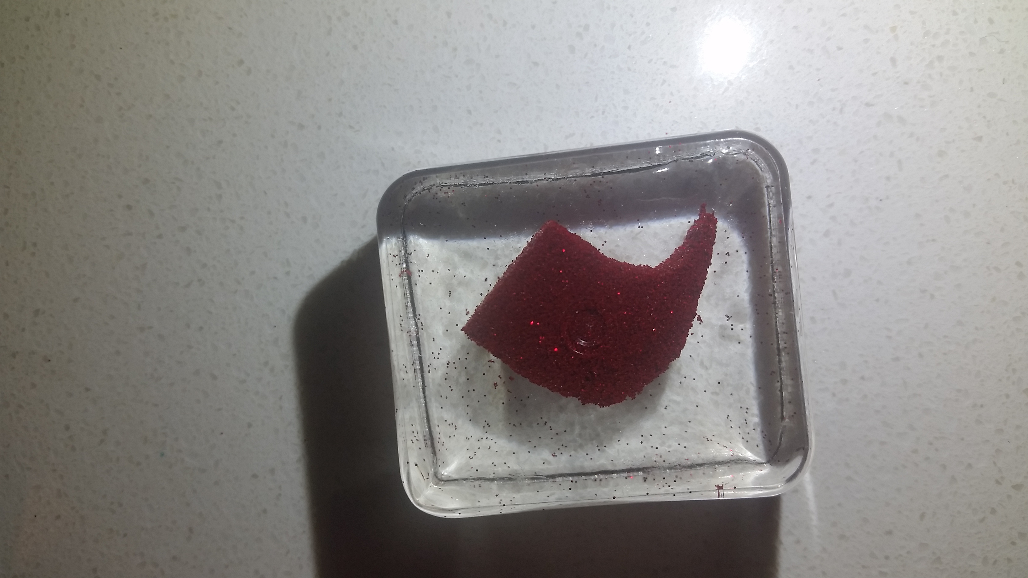
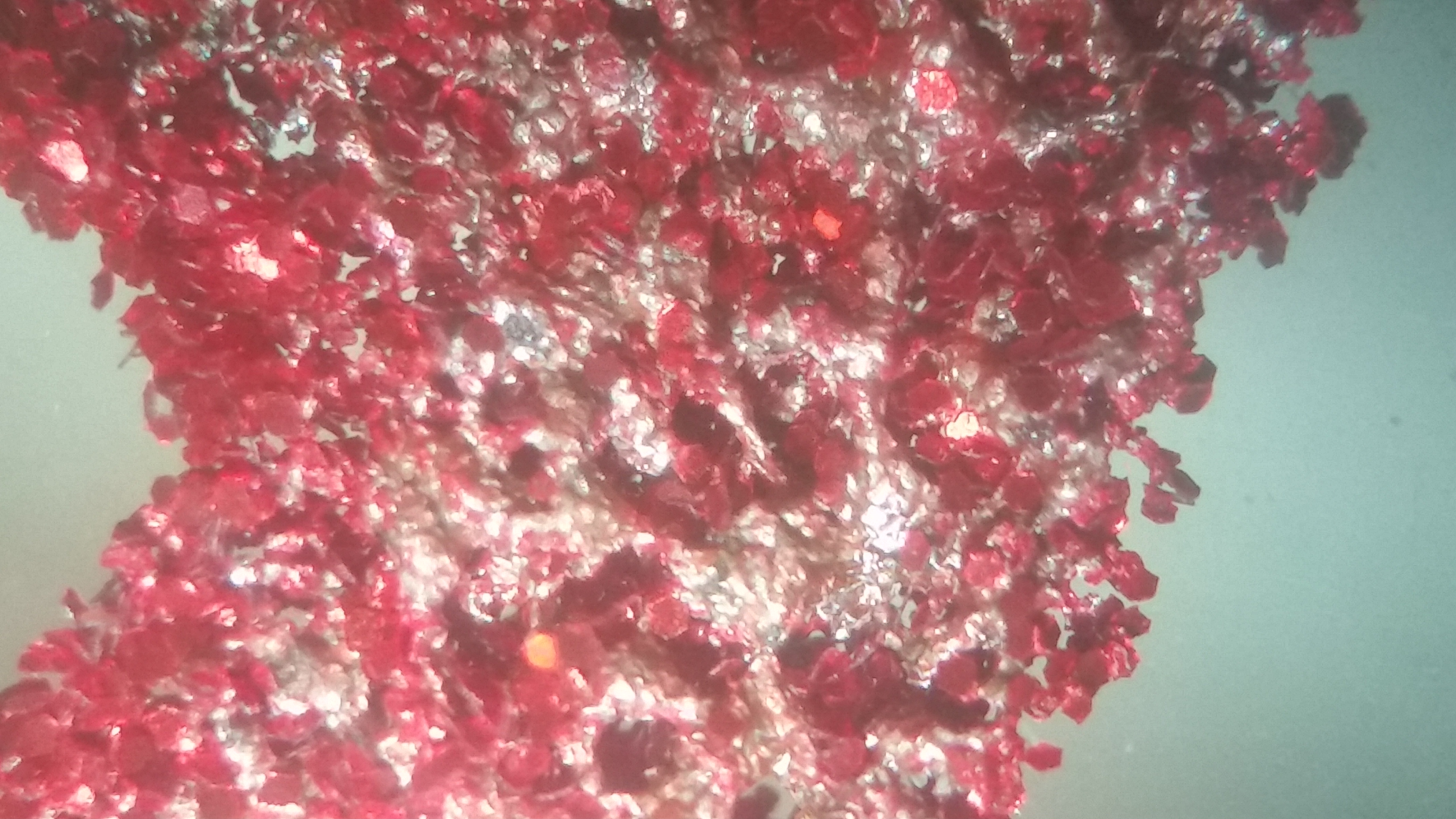
I’ve managed to balance the tradeoff of having no slippage, a decent speed, and enough strength to stay together, but the parts are far from useful. I casted them in clearcast resin to prevent them from falling apart in transit. If you look at the parts under a microscope, you can see that the surface of the parts looks like swiss cheese; I need some way to fill those voids or melt the glitter more consistently or I have no hope of gaining any strength. An infiltrant like melted wax or resin would work, but I’m stubborn and adamant about making the parts pure, unadulterated glitter.
I unveiled this machine at the 2018 Midwest Reprap Festival (#MRRF2018) in Goshen, Indiana, and got a great response, including a mention on Hackaday, 3dprint.com, OSHPark, and several youtubers, including Tom Sanladerer and Joel Telling (17:45). If I can make more progress on it, I’m hoping to take it to the East Coast Reprap Festival in June.
[Update 4/7/18] While most of the feedback I got from this was very positive, I seemed to have rustled the clipboards of OSHA-loving safety people who criticized my lack of safety glass covering a Class IV laser being shot at a million tiny mirrors. It counter this, I’ve covered the acrylic with yellow welding curtain, which, while not perfect, will filter out almost all of the UV and most of the blue light. Still got to wear safety glasses, but it’s good enough that it wont just randomly blind someone walking by.
Pros:
- Only device in the world that I know of that 3D prints in 100% pure glitter. Got to get girls into STEM somehow, I suppose.
- A revival of an ancient piece of 3D printer history to be useful for something again.
Cons:
- Literally everything in my house is covered with glitter.
- I’m covered in glitter
- Strength of material is really, really weak. It does stay together, but it will fall apart if compressed.
- Larger parts warp enough to get pushed just a little, so between layers, the part will move a little, resulting in layer shifting. This is less pronounced with smaller parts.
- The front panel is completely nonfunctional. Not sure quite why I haven’t gotten around to it, but I haven’t wired it in yet. I’ll get to it eventually.
Opportunities for improvement:
Material properties is the big push at this point. “Thermal properties of melted glitter” is surprisingly lacking in the research department, and I may actually be the foremost expert in the field.
The PID controls for the motors work, but are not tuned, and as such, the whole machine vibrates and sounds like a car engine. I’ve got to fix that at some point, but I’m afraid I’ll mess up what I already have. [update 3/26/18, this is mostly fixed, but still need a bit of work on the X axis]
The biggest thing I have to fight is warping. I’m trying to avoid heating the build chamber, but I might need to. Maybe a bigger laser would help, but I’m not sure on that one. I’ve ordered some 0.004” glitter flakes, and I’m going to see if I have a better response with that. I’ll have to look more into polymer research to get a better understanding of exactly what is happening.
I’m currently trying to negotiate a way to purchase a small quantity of very small glitter from the manufacturer (Meadowbrook Glitter), which may be smooth enough to get a better, cleaner, stronger infill. Stay tuned.
Conclusion:
I love this project. It’s messy, its fun, and I get to complain about the difficulties of sourcing massive quantities of glitter. I get to go to the store and buy 10 bags of confectioner’s sugar and mix it with 5 pounds of chocolate powder, blast it with a laser and call it engineering. But most of all, it has potential. If I can get a working SLS machine that can produce useful parts, I can make pretty much anything, and even though its based on a Zcorp, once the software works, and works well, nothing says this cant be used to make a fully open source SLS printer that other people can optimize and drive the home-based additive manufacturing industry forward. Who knows? So next time you open a sparkly greeting card or get hugged by your niece dressed as a fairy princess, just know that a great engineering project can come from anywhere.
Photos available under CC BY-SA 4.0
I added your project to the Wikipedia article for Z Corp https://en.wikipedia.org/wiki/Z_Corporation
Dude. I found your project this morning, after finally getting around to Joel’s coverage of MRRF, and I gotta say: Holy Creative Carpeting Batman! This is so awesome! Can’t wait to see where this goes. Keep it up!
“I came across an idea. A horrible idea. I wonderfully horrible idea.
Glitter”
I was LMAO .. that was Superb!
Others were looking at me as I was laughing so hard!
Project idea – 100% ..
Project Humour – PRICELESS
Please could you upload a photo of a Benchy to Wikimedia Commons so I can add it to the Wikipedia article? Let me know if you need any help
John,
Wikipedia is always a cool thing to be added to. Images are a bit lacking, but I have a few:
http://scottziv.com/wp-content/uploads/2018/03/IMG_0227.jpg
http://scottziv.com/wp-content/uploads/2018/03/IMG_0234.jpg
http://scottziv.com/wp-content/uploads/2018/03/IMG_6062.jpg
http://scottziv.com/wp-content/uploads/2018/03/glitterbenchy2.jpg
The printer is currently down for a laser upgrade, but if none of these are sufficient, I can fire up the printer again and make another one.
Thanks very much Scott, sorry to not come back and see these till now. I need to be able to point to a license to be able to upload them. Could you add a note at the end of the blog that just says ‘Photos available under CC BY-SA 4.0’ Feel free to email me if you have questions (I guess you can see the email addresses when people post comments).
Also best of luck with the upgrade, I feel like a lot of the work you’ve done on this could be used to create a RepRap SLS machine, I really hope someone will pick it up…
Thanks
Sorry this took me forever; for some reason WordPress stopped pinging me. License added.
Dear scott. This is very good project. congratulations. I am glitter powder producer, We have different type of product and I think it will be work on your machine better than normal pet glitters. Heat transferable glitter powder. this glitter have holmelt adhesive on one side and other side is PET. hotmelt glue activete with 150 degree celsius heat. If you interest pls contact with me