Pictures:
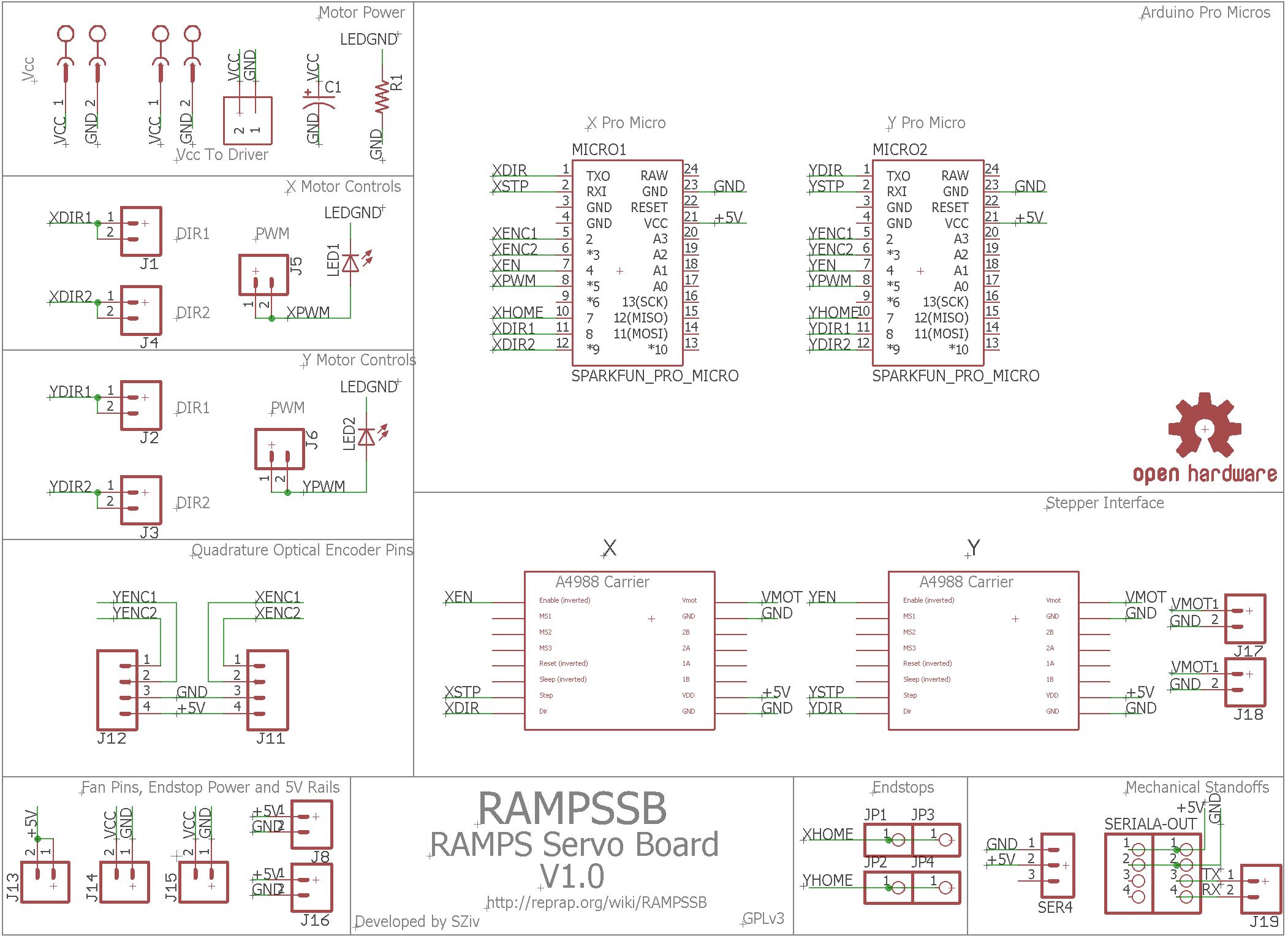
^ Main Board Schematic

^ Layout
Skills used:
Eagle, Mechatronics, Electronics, Control Theory
Description:
While in the middle of working with the RAMPSXB, I was still tossing around another idea in my head: Closed loop motor control. Before I get into the details of the actual board that came to be known as the “RAMPSSB” or “RAMPS Servo Board,” a quick 4 paragraph 3D printing history lesson:
People often ask me what I think the next big feature will be in consumer printers. My answer is that it will probably look something like “verified” or “self corrected” printing. Almost all so-called “easy to use” machines or cheap Chinese 3D printers use stepper motors, which are nice because they are very easy to give a certain distance of movement. However, they are open loop control, which in layman’s terms means that if the head gets knocked out of place, it wont know it, and you end up with layer shifting, resulting in a failed part. In the industrial realm, this “verification of quality while producing a part,” more commonly referred to as “in situ monitoring,” idea ties into a larger system called statistical process control (SPC), which in turn is part of a huge manufacturing buzzword called a “digital thread.” There’s a lot of YouTube videos on that, so I won’t go into it.
But makers and consumers don’t really care about that. They just want their printers to work, and spit out quality parts every time. If the people reading this blog post are who I think they are, you’ve probably taken apart at least one inkjet or laser paper printer. You’ll notice that unless the printer was made in the stone age, it doesn’t use stepper motors, but rather a geared DC motor with some sort of encoder on it. Why? Well, because it’s cheaper, and often times, are faster and may be more accurate. Moreover, if you let the printer print, then force the head out of position, it will bring itself back, in a closed-loop system.
Wait, hold on! Both makers and home consumers like cheap, accurate stuff. Why aren’t consumer grade 3D printers using DC motor controllers? Well that lies in the history of 3D printers. After Stratasys’s patent on FDM ran out, a project called Reprap started up, and it was basically trying to make a robot that could reproduce. Because 8 bit microcontrollers were all the rage in 2013-2015, the reprap defacto standard was to use Arduino microcontrollers because of their ease of use and low cost. That resulted in all the common firmware being written in Arduino’s bastardized C++ variant. Just one problem. 8bit processors are relatively slow, clocking in at around 16MHz. Since reading an encoder takes a bunch of interrupts, a 16MHz processor just isn’t fast enough to read 2 or more encoders, take in serial data, calculate motion, and make sure everything is in the right place.
In early 2016, the control boards started branching out into other microcontrollers besides the ATMEGA, such as the cortex M0, Attiny, or STM processors, but they only really support programs that can be built on the Arduino platform (you don’t see any MSP432 3D printers do you?). These days, 32 bit architecture like the cortex M0 or STM32 is very clearly the future of 3D printer controllers, and while they can handle the processing speed required for reading encoders, it still not very easy, and the risk of missed steps is too high. Some closed loop stepper motor controllers (namely the Mechaduino by tropical labs) started coming out, which did the processing using another microcontroller. As a reprap developer, I’ve seen a few attempts at a black-box converter that would take step, direction, and enable pins used by most stepper motor controllers, and, using a quadrature encoder, control a DC motor to make the same motions in a closed-loop system. Of the three attempts I saw, many were either disheveled messes of wires and haphazardly soldered boards, or were praised as an all-in-one solution that either was never released, or faded into obscurity. Scrolling through the RepRap wiki doesn’t yield anything, and a google or ebay search of “stepper motor to DC motor” doesn’t help either. Most of these projects seemed to just die out.
So what does that history lesson have to do with the RAMPSSB? Well, were others may fail, that means it’s time to step up the game. The engineering need (or in this case, the want), was a way to use these closed loop DC servo systems with a standard 3D printer control board (surprise!). All 6 of my printers run off of a RAMPS system, because it is cheap, open source, and easily modified, and most of the 3D printing world uses it, so I chose mainly to support that board. Other needs were:
- It had to natively support RAMPS (preferably with no modification), but also be usable as a generic “step/direction/en -> DC motor converter” for other systems, since there doesn’t seem to be one.
- It had to be cheap, which can be done by using off the shelf components instead of using custom ones.
- It had to be manufacturable with just a soldering iron.
- It had to have an accuracy at least within the realm of stepper motors.
- It had to support at least 2 axes.
- Can support 24V motors
- Doesn’t require motor modification, like some closed loop systems that use the AS5040 do (matching the PCB to the motor, attaching a magnet, etc). I just want to buy a quadrature encoder motor off Ebay the size I want and just run it.
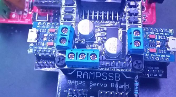
While RAMPSXB was almost brainless, just taking the systems of the RAMPS board, coping them and reorganizing them, this one took more thought on how to make it work. Taking a nod from the plug-and-play idea behind the Mechaduino, I decided to make each axis controlled by its own processor, so I could use a relatively cheap ATMEGA, and because of the sheer amount of interrupt pins required. I also knew that most of the Chinese L298N DC motor drivers are all standardized, can provide up to 2 amps per each of its two channels, and have a built in heatsink. Because I order most of my boards from SEEED Studio, who offers them for $5 if they are less than 100mm X 100mm, I wanted something I could fit in that area. Also, since there is rarely skipped steps in the Z axis, I only needed 2 axes of control, X and Y. Anything more than that would be superfluous, but if necessary, I could just wire the pins to another RAMPSSB if I needed a 3rd or 4th axis (I’m looking at you Deltabot people!).
So I hit eagle, and after a few design revisions, I came up with a board I was happy with. It uses two Arduino Pro Minis (designed by Sparkfun, but there are plenty of clones for ~$5 each), which were chosen because of the cost and need for 5 interrupt pins (encoder 1, encoder 2, step, direction, and the endstop). The L298Ns are a mere $3, so I affixed one with 3 standoffs above the Pro Micros. And that’s about it. With the exception of the PCB, some jumpers, LEDs, a resistor, and some header, that was all that was necessary to make a completely standalone DC-motor control board. Just plug in any old DC motor with a quadrature encoder, shove it in and go. There was some firmware modification required, but most of it was copying numbers from the RAMPS’s firmware, and setting PID control coefficients.
After I got it assembled, I hooked it up to the Y axis of an old Zcorp Z402 (500ish RPM, 2000 counts per revolution), and, while it did wobble a little bit, it mostly behaved. Below is a quick demonstration:
This project is open source, and posted on GitHub here, and assembly instructions and documentation are up on the RepRap wiki here.
[Update 11/30/17]
After talking on the Reprap Forums, I’ve made a single channel version of this board, StepServo: https://github.com/SZiv/StepServo
This board takes more wiring, as it doesnt fit directly into the RAMPS, but its much smaller, and everything fits underneath the Motor driver, so it’s much more compact.
There is also talk of making a DC motor/encoder Extruder. Stay tuned for that. Because of how darn powerful gearmotors are, and how they can be mixed with any speed gearbox you want, they can go much faster than steppers. Combined with RAMPSSB for the X and Y axes, its very possible we can see 3D printers going at extremely high speeds without missed steps. Take that Michigan! (even if you are liars)
Pros:
- It works! And it’s closed loop!
- Kind of bulky and tall, but actually relatively small in size.
- Surpisingly simple to use. There are only 3 or 4 numbers that need to be changed in the firmware to make it match any hardware setup, be it belt or leadscrew based.
Cons:
- It’s a little shaky, and even after some PID tuning, it doesn’t behave as perfectly as I would like.
- I haven’t built a system to test it in action yet. It may not print with the same precision as a stepper motor based system.
Opportunities for improvement:
There definitely needs to be some firmware work done on it, but I haven’t yet learned enough control theory to make it work perfectly. It’s released open source so more eyes can go over it, and maybe someone will be able to point out some flaws in my logic.
I also have plans for a similar PCB that uses quadrature encoders and stepper motors instead of DC. It would be a lot more familiar than DC motors, and while I think it would be a step backwards technologically speaking, it would be more of an “upgrade” as opposed to a “complete overhaul,” and it could use a single channel, as opposed to a two-channel system. Not sure if or when that will ever be completed, but it shouldn’t be too much to work on now that the hard board is done.
Conclusion:
Overall, I think this was a lot of fun. I’ve been interested in control theory for a while, but never really got a chance to work on a real system before, and this was a great hands-on experience with board design, PID, and DC motor controls that I never really got in college.
As for the actual final product, I would say that the hardware is good, but the firmware needs some work. As I learn more and get suggestions from the community, I will continue to support this board and make changes and firmware updates.
This is actually part of a larger project to overhaul my Zcorp Z402 to convert to Reprap, since it uses 2 very large DC encoder motors. More info on that as it develops.
Very interesting. Something I will be watching closely I would like to see a full closed loop system with an adequate amount of axis and extruder connections. Preferably 7-9 would be great for multi axis, multi extruder use where someone may want to use encoders on the extruders as well. Currently building one with closed loop motors on the 3 axis that only results in feedback tonthe drives. Still an upgrade from the current setup not requiring too much code modification. Hope to see the community take this idea farther and deliver a product that works in a high mm/s print speed with high accuracy. Nice work keep trucking along you’re now a developer.
This is going to be a starting point for me. (when I finally have time to get started)
A few years ago I was able to get some parts off an old pick an place machine. There were two heads on the gantry for placing parts. Each had a 24 volt 1.9 amp dc servo with 1000 step encoders. 3000 rpm max rated speed.
I was thinking of doing a small CNC router project but the motors are too small for that. (unless I use a Dremel) The other think I was thinking of was a coreXY type machine.
I have already picked up some L298N driver boards. Something to initially play with. I have a STM32 “Blue Pill” board that I was going to use but I have never played with it yet and I expect there to be a learning curve. I have lots of promicro boards so your project could get me started a lot quicker.
Rudy,
Yeah, this setup is designed to be functional and cheap.
If you’ve got questions, let me know and I’ll try and help you out.
-Scott
Great work, I am thinking along the same lines, are you aware of ServoStrap? Maybe it you can adapt that for your firmware– see GitHub
thank you!
“it doesn’t use stepper motors, but rather a geared DC motor with some sort of encoder on it. Why? ”
At the main is cost. But printer has full linear move against CNC.
The PID control good idea, but want the best. I think that problem in the convertation step/dir to pid/pwm, its not right, we are needing in DC-motor driver instead Stepper. Yes Stepper drive have trapeziod mode (acc-move-deac) like DC, but need replace it with new calculation (RPM/Dir instead Step/Dir). Also using DC motor for extruder its main task for me. I think that Stratasys Mojo have good idea with low cost 130 geared DC-motor + encoder for the length of material instead encoder on motor.
This is really a very good project which i was searching for. It is because there is no extra load on Main microcontroller to write interrupts and make a big firmware instead just write normal software as many axis and go on adding individual drivers. Thanks.