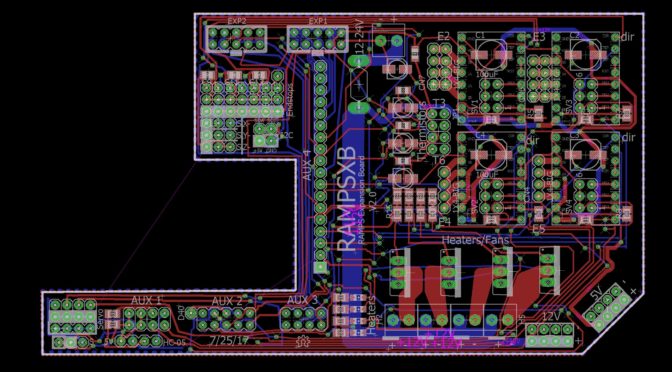
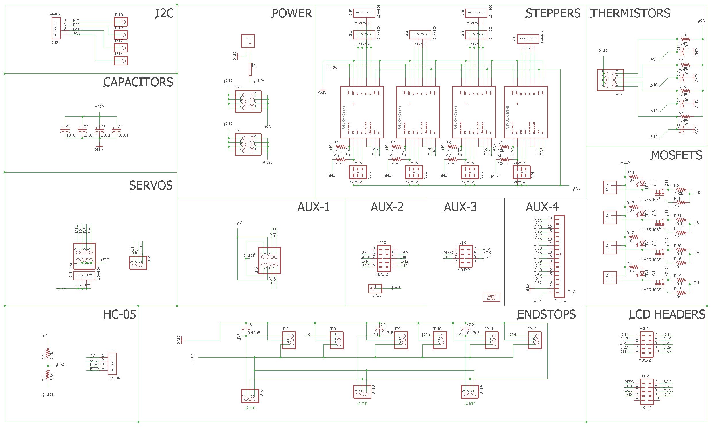
Pictures:
^ Current version, V2.1
^ Schematic
Skills used:
EAGLE
Description:
How many Extruders is “too many”?
Over in happy-fun 3D printer land, there is a really, really, common control board called a RAMPS 1.4. It has some flaws, but due to the fact it doesn’t contain any ICs except FETs, is open source, dirt cheap to make, and has more than enough functionality for most starter machines, it is actually the world’s most common 3D printer control board. Its also considered to be one of the worlds worst control boards due to the slow processor and shoddy overseas manufacturing.
And, unfortunately, I don’t really live in happy-fun 3D printer land, as I’ve been working on some stuff that requires many, many extruders, and a lot of fans. By default, the RAMPS has 2 extruders built in, and you can buy stepper expanders, that add one, two, or 3 steppers. However, what if I want 6 individual stepper drivers, with their own heaters and thermistor. Short of hitting a protoboard, or buying an expensive replacement board, there isn’t much in terms of options.
With that in mind, I wrote a list of gripes I had with the RAMPS 1.4 system:
- MORE HEATERS
- MORE STEPPERS
- MORE THERMISTOR PINS
- Prewired HC-05 pins (the Bluetooth RX pin needs a voltage divider to get from 5V to 3.3V)
- Suppression capacitors for the endstops (Used by the RAMPS 1.4.2; magnetically induced signals from the motors can cause the print to fail with a false positive. Mostly happens to CNC machines, but worth noting)
- More 12V and 5V Rail pins.
- Header connections for the LCD screen
- Usage with 24V
With all that noted, I got a suggestion from a friend to try learning EAGLE. I had tried KiCAD in the past, but I couldn’t figure it out. So I downloaded EAGLE and gave it a go.
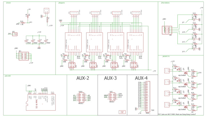
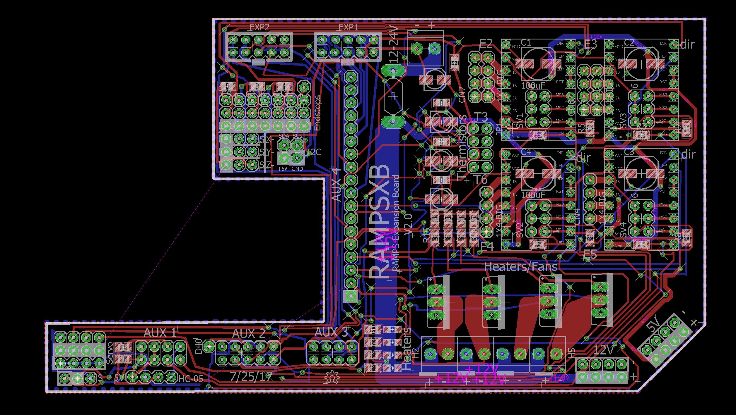
The RAMPS board has 6 sets of pins, AUX 1, AUX 2, AUX 3, AUX 4, SERVOS, and the Endstops. I used the LCD Screen a lot, which requires AUX 4 and AUX 3. Without wanting to take up too much of the pins, I decided to just consume all the pins on AUX 4 and AUX 3, but also wire in an SD card, since that used much of AUX 3. Arduinos use PCBs called “Shields” to expand capability. Even the RAMPS is a shield (Reprap Arduino Mega Pololu SHIELD), so it only made sense to make another board that stacked on top of the ramps headers. After a bit of YouTube tutorials, I was up and running, and made this:
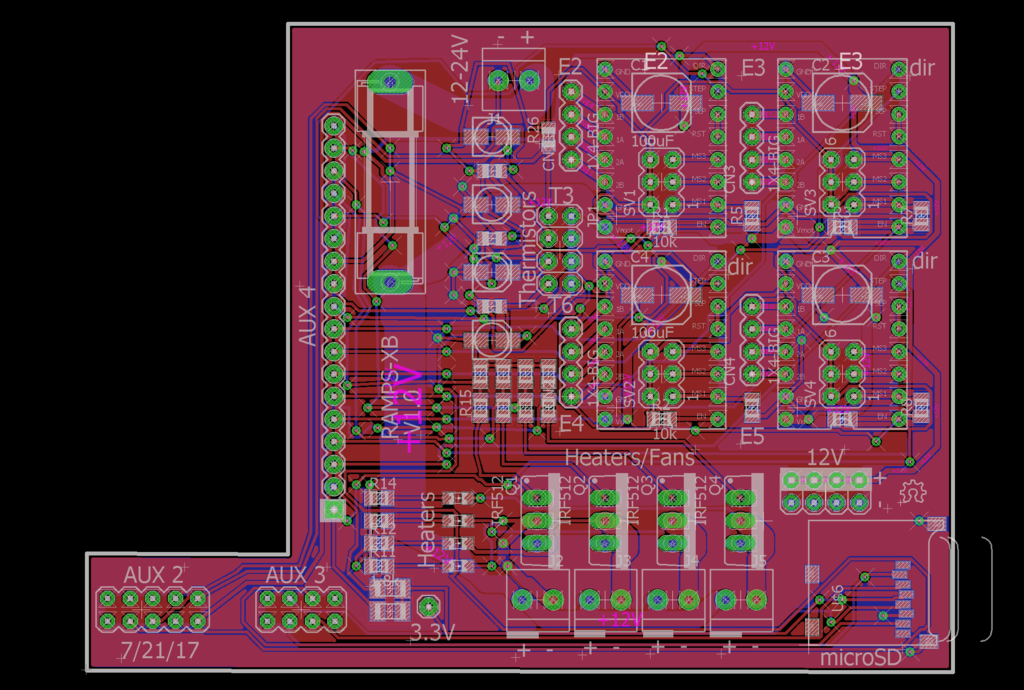
The RAMPSXB (short for RAMPS eXpansion Board) It had the 4 FETS, Thermistors, and Steppers I wanted, but that’s about it. Some of the traces were a little weak on the Heater pins, but I couldn’t do much about that. Eager to try them out, I ordered a set of 3 from OSHPark.
But, as engineers know all too well, as soon as I placed the order, I found a flaw. The Heater pins were wired to digital pins, not PWM, so I could only turn the thing on and off instead of variable. This is usable but not ideal for heaters, and is unusable for fans. In addition, the microSD card pin was correctly wired to a 3.3V power rail, but lacked a logic level shifter for the digital pins, meaning any SD card that was plugged in would be fried as soon as it was accessed.
Well, shit.
Back to the drawing board, I went back to my list of wants and said “Hey, since a lot of people will be working with the RAMPS board, they may find this useful, so let me just add everything that I think people would want.” So I did. I expanded the size of the board (above the 10cm limit on many manufacturers. Sorry), cut out the space on the board, and consumed all 6 sets of header pins. After wading through some terrible documentation on the LCD controller I used, I managed to get the two headers I wanted, as well as all the steppers, thermistors, full PWM heaters, the Voltage divider on the HC-05 (as well as broke out the pins in order), the 4 sets each of 12V and 5V rails, and the suppression capacitors for the endstops, and just for shits and giggles, I gave two of the four steppers 2 sets of output pins, so the signal can be mirrored on two motors. The functionality cost for all this? The max endstops had to go (which no one used anyway), and 3 of the 4 servos got axed.
It took me a while to get all the wires together, but In the end I put together V2, in the pictures section above:
Much, much better.
I am waiting for my first set of boards to come in so I can fix any issues I find there before I order the next set, but I’m interested in seeing how it works out.
I published the current version up on Github here under a GPLv3 License: https://github.com/SZiv/RAMPSXB
[Update 8/8/17]
Alright, the first version board came in. I couldn’t really test any of the new features like the LCD or PWM, but the actual stepper and FET systems do work; they were rerouted to different pins on the new version, but luckily there wasn’t any interference.
I also realized that I was a moron and forgot to level shift the SPI for the SD card down to 3.3V, so any SD card that goes in that slot get instantly fried. Whoops! I have removed the old version of the board from github to prevent this from happening to anyone.
[Update 8/20/17]
Version 2.0 of the board has arrived from OSHPARK, and I’ve got it assembled. it passes almost all of my preliminary tests, but I have fears about the tracewidth of the power traces.
[Update 8/22/17]
Exposed the copper on the bottom power traces, so they can be covered in solder to increase the current to reasonable levels.
[Update 8/23/17]
Development documentation has officially begun! I’ve begun work on writing up official documentation on the RepRap wiki page here: http://www.reprap.org/wiki/RAMPSXB
[Updates 8/27/17]
Found a major issue in the design. 5V on the arduino was wired to GND on the board, which was tied to GND on the arduino. This has been corrected in the newer version, 2.1, up on Github now.
[Updates 9/29/17]
Version 2.2 was created, but a major defect was found due to poor documentation of the Reprap Discount Smart Controller. In other news, I found a manufacturer to produce the boards. The version being shipped will be version 2.3. This version is functionally identical to version 2.1 (which has been retroactively corrected), but the MOSFETs will all be surface mount for ease of production. I will post a link to the item when it is available for sale.
Until further notice, I intend to support both version 2.3 and 2.1, with version 2.3 being the priority.
[Updates 9/29/17]
Reprap.me, a website that sells reprap boards and parts, has begun selling assembled versions of the RAMPSXB. Check it out here: https://www.reprap.me/rampsxb-ramps-expansion-board.html
Pros:
- Adds a lot of functionality to a board that runs most of my 3D printers
- Finally, I can fix endstop false positives
- Is open source, so anyone can make this if they want.
- Is built off the RAMPS Schematics, so all the Heaters, thermistors, and steppers should behave the same way. Just set the pins!
Cons:
- Who the hell needs 6 extruders?
- There is a fuse, but no room for diodes for reversed power safeties. Don’t screw up.
- Thin, close together traces may cause interference with each other. I’ll do testing on that.
- Is larger than the 10cm area mark that many manufacturers want to see, so price jumps up significantly unless you order in volume.
- I have fears that the Arduino running the RAMPS board won’t be able to process the 12 extra sets of data.
- My first foray into EAGLE, and I have a feeling I messed something up without knowing it.
Opportunities for improvement:
I actually cant think of any. I’m generally a very self-critical guy, but aside from maybe checking for traces that are too small (all minimum features are 7 mil, which is good enough for most manufacturers), or fighting inductive signal muddling (A big issue I’m afraid of), I cant think of any more issues I can resolve or features I can add to this thing without driving the price up unreasonably. Maybe larger traces for the heaters so they can power heated beds?
Conclusion:
Let me start by saying that very, very few people will actually need this board. This is like going to a car dealership and saying “yo can you give me 5 spare tires.” There is nothing wrong with it per say, but its way too much for the average user to make full use of, and most of the people who need this will either upgrade to a Duet board (which costs ~150 buckaroos), or just make their own versions of this. This is for some seriously messed up engineers who want way more out of their machines than the price bracket they bought it for is good for.
That being said, Nothing says that this board WONT work, and for some high end hotends like the E3D Kraken (4 extruders w/ temperature sensing and individual heaters), or the new Reprap Full Color Diamond Hotend (needs 5 extruders, but one heater and thermistor), this is actually closer to right than the original, unmodified RAMPS.
More info to come after testing.

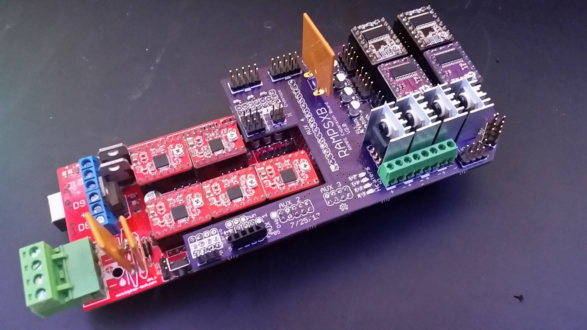

Response to Alex, whose original post is here (http://scottziv.com/about-me/resume/)
Why did I make this? Well I came up with the idea about a year ago, but didn’t know enough about PCB design to actually make anything out of it. When I decided to learn eagle, this was the first project that came to mind.
I’ve actually found a manufacturer who is looking to mass produce full SMD versions. We’re in talks to get some optimized prototypes made using the newest version of the RAMPSXB.
This was my first major EAGLE project, and I’ve been looking to learn more about design for PCB manufacturing, while still juggling the maker mentality of “Let me do it myself”. I settled on the current design using SMD Capacitors and Resistors because those can be pretty easily soldered by hand with a soldering iron. The newest design uses SMD MOSFETs, but I also have and intend to maintain the github for a through-hole MOSFET design under old designs/V2.1.
I am waiting on the (hopefully production grade) version from my potential manufacturer, and if that all goes well, I can try making a fully through hole version. The biggest issue with through hole is size, and size is very, very tight on the RAMPSXB, and through-hole takes up space on both sides of the board.
Maximum current is going to end up being limited by the wire traces. As of now, the traces running to each of the heaters is 100 mil, which should be enough for 5 amps per FET. Assuming the terminal blocks don’t melt (which may be fixed by just wiring the wires to the hole directly), it should be enough to run a 24V, 5A heater intermittently, so 120W, which is 3 times more power than a standard 40W heater. The main power traces are also 100 mil, but those traces are exposed, so solder can and should be dumped on them to increase the current they can carry.
750C hotend is coming along, but I’m having the issue that its 1.5kW and blowing the circuit breaker in my house. More information will be posted here once I actually get it to work.
Microwave melding probably wont work, because microwaves work by rapid flipping polar molecules in a substance. It works on food because water is a polar substance, but most plastics are not. Perhaps some way of getting the plastic wet or using metal infused plastics?
I do like the idea of printing in an oven, but remember that solder melts at 190C, so all your electronics need to be outside the machine. In addition, the plastic in a stepper motor will melt down before that, so you either need to move those out, or use liquid coolers.
Sorry for my poor English,
If I read clearly your plan and pinout, why don’t you use a second ramps ?
In fact in my mind will the result be the same if I simply plug the right pin of the Aux, for exemple, of the first one on the needed entry of the the second one ?
Ok with this method , we just have the 3 thermistors in place and not 4 .
But we have at least the 4 more extruders, etc…
Best regards
Absolom,
That’s certainly doable, and will achieve the same result, but that’s a lot of jumpers to route. I ran into the issue making the RAMPSXB that I used ALL of the aux pins, so you’re talking a good 30-40 jumper cables wired from one RAMPS to another. Nothing says you can’t do that. Hell, nothing says you can’t use jumpers to connect directly to the stepper drivers; The idea here was to add a lot of functionality in an easy to use package where you just pop it on and install the firmware. The RAMPSXB board’s a bit pricy (I think it’s being sold for something like $40), but its a lot cheaper than something like a duet, and with more ease of use than hardwiring an $8 RAMPS. Just a sort of middle ground.
hello can we still plug a bltouch knowing that I’m not screen on the printer?
The site http://www.reprap.me do not sell rampsxb .! Where I find rampsXB ?
I live in Brasil.
(My English is very bad)
Thanks.!
There arw currently no sellers unfortunately… I’m hoping that since it’s open source, china will pick it up and start producing.
I want to custom order this. Do you know a good place that will assemble the board not just the PCB? I’m really not experienced with SMT components besides looking up a fried part number and soldering a new one when I fry it. I would probably buy the wrong parts. I don’t even know if the schematics have the SMT components in it.
David,
I do not. They used to be made by RepRap.me, but they got discontinued, probably because the market buying them was so small. I know there’s quite a few of these out in the wild, but i’m not aware of anyone else producing them.
If you do find a way to produce them, or find someone willing to sell them, let me know; I’d be happy to do documentation/BOM lists if that’s what it takes to get it to production.
I have found someone 7pcb.com that will make them but I know fairly little about this and so in talking with their quotes customer service the BoM list needs voltage ratings for the caps. Wattage ratings for the resistors OR manufacturer part numbers specific to the parts you got. I was looking to have it run 12v or 24v since I’m soon to move to 24v so thats likely to be different than what you initially built. quotes@digikey.com stated they can provide help if the voltage and wattage is stated and they will provide help with Manufacturer Part Numbers. I don’t expect the boards to be cheap but we’ll see. Minimum purchase is 3 Units. I can state I want caps like the ones I have on my RAMPS with a higher voltage than I need like 32v-36v but the wattage on the resistors I have zero clue how to figure that out. So I’d like your assistance. Thx
I believe if I’ve done this right. Have calculated the minimum wattage for each resistor on a 24V system. 24V / Ohms =Amps * 24V = Watts. But I wonder if the packages will still fit in the design if the higher wattage rating increases the size of the packages. Plus I want to add a little more than just the minimum for safety. Idk if resisters have like a standard scale to pick from for wattage ratings. I’ll have to wait and see what you have to say.
Bump?