Pictures:

^ The Inventor model of the the gantry system.

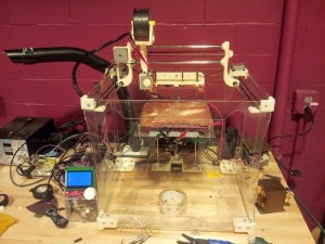
^ The printer in full. The testing transformer can be seen to the lower right of the image.

^ The brilliant arc flash of a 3D printer printing steel.
Skills used:
Autodesk Inventor, Marlin Firmware, Mechanical Design, Electrical Engineering, Welding.
Description:
So I have been interested in 3D printers for a while, and I decided to build one. However, I did not want one a common one like a Delta or a Reprap. Many of those are too small for what I wanted to do. My requirements for a printer are at least 200mm x 200mm x 200mm build area, decent accuracy and fairly cheap to build (< $500). Oh yea, and I wanted it to print in ABS, PLA, and steel. Since I could not find anything within my price range that could print in steel, I decided to make my own. I needed a name for my custom printer, so I called it a PISCES (Progress-of-Ingenuity Sampling and Constructive EngineeringSystem).
Alright, Step 1: Design a method of printing metal. Most additive manufacturing devices that print steel use Selective Laser Sintering (SLS) technology. However, this is completely out of my price range, and moreover, this would not allow me to easily switch between thermoplastics and steel. So what about a crazy idea… Why not print steel in an FDM process? I know what you are thinking: “But Scott, steel is a hard substance with a higher melting point than ABS, you won’t be able to extrude it.” Maybe not, but I can adapt an extruder to become a wire feed, remove the tip, and I can use a DC electric current to melt it at the point of contact with the baseplate. This idea came about after taking a college welding course. The process of MIG welding with flux core welding wire works practically the same way… with a few modifications. This is the basic schematic for the design:

After I had an idea where my project was going, I used Autodesk Inventor to CAD a basic gantry system that has a spool holder on top of the extruder head. I used the Frith Lab’s laser cutter to cut the side plates out of 0.2″ acrylic, and its 3D printers to make the parts. After installing a RAMPS1.4 board and adapting Marlin firmware to fit the need, I started running ABS filament. This worked fairly successfully (it was not perfectly calibrated), but it worked well enough to move onto the next stage of implementing steel.
I then started thinking about how I could melt steel to a ground plate. I put a copper plate on top of the heated bed (so the steel does not stick during testing), and ran that to a microwave transformer, and attached that to a diode so I have a somewhat DC current. As of now this is 2100VAC at 0.57A (the reason for such low amperage for testing is so that I can use easy-to-maneuver, high-gauge wire without it melting). I have a second transformer wound to output the 65A, 18V needed for MIG welding and a couple Schottky diodes on order in order to make a bridge rectifier, but I am waiting to put that on until later.
And then, suddenly, a hiccup in my design. I was using a high voltage transformer hooked up to a HV diode to make a modified, positive-current-only circuit for testing (because it is easy to see when it works). It turns out that leaving the grounded heated bed wired to the RAMPS board while the transformer is running runs an AC current all the way from the extruder head to the bed through the electronics, causing my thermistor to turn into a lightbulb, and then into a fireball. I have since corrected this issue, but I have yet to replace the thermistor, because I want to get everything else running for fear of burning it out again.
There is still a lot of work to do, but progress has been made, and the proof of concept is there, and besides, no good project is ever really done. Now, where to order a few hundred more thermistors…
[The files for this printer have been made available here.]
Pros:
- It was fairly cheap to make, costing only around $400 for a build area of 8.25 x 8.25 x 10, not counting the cost of 3D printed ABS material.
- I was not intentional, but the machine ended up looking, aesthetically, pretty good.
- I learned a huge amount about 3D printers, Marlin, electronics, etc.
- I have more CAD practice then I ever thought I would get on a single project.
- 3D printing steel in an FDM process opens up a world of possibilities unimaginable for thermoplastics (Printing silverware, circuits, etc.).
Cons:
- The Catch-22 of needing a 3D printer to print a 3D printer.
- The plates were cut with a laser cutter, which just is not that easy to get access to.
- The whole case is huge, and takes up more space than it probably has to. This also allows air drafts which may cause ABS parts to peel up.
- The modified DC current used for the welder has damaged the electronics before,
- MIG welding throws sparks in all directions. I need to put a cover on to prevent the entire thing from becoming a major fire hazard.
- The light produced from the welding tip is blindingly bright. Anyone nearby will need to wear welding goggles to prevent blindness.
Opportunities for improvement:
Well for starters, the calibration of steel will be difficult. Heat management will be brutal, especially since the whole machine is made of plastic, and I may need to implement breaks into the G-code in order to allow the part to cool for some time. If the feed rate is too high and the steel gets stuck to the plate without initiating an electric arc, getting the wire off may be a challenge (perhaps adding a new G-gode command to discharge a capacitor to blow up the remaining wire?).
I need to find a way to lower the light output. The electric arc is blindingly bright (ever wonder why welders wear welding helmets?). I can put covers on the side plates to reduce this, but then it would be difficult to see the part. I am hoping that lowering the voltage will correct this, but I may need to implement a light filter into the plate system.
And there there is the whole idea of design for additive manufacturing, which is a field of study centered around how to designing a part to best be build on a 3D printer. Using an electric current adds a whole new level of complexity to the mix, as this requires that the wire feed be the smallest point of contact between the extruder head and the baseplate, so small features are out, and cohesion between liquid metal will be an issue as well.
Conclusion:
It is a good start to an interesting idea. It already runs ABS plastic pretty well, and some safety limitations need to be put in place when dealing with such high amperage, but the proof of concept is there, and I am working to get it up and running with steel successfully.